The right insulation for aluminum melting-holding furnaces should reflect actual operating conditions, which may include higher heat levels as a result of efforts to increase productivity.
 Monolithic refractories provide optimal productivity and cost effectiveness for melting andholding aluminum. Various products are available because as aluminum furnaces have particular operating conditions compared to other refractory applications, suppliers have to offer specifically tailored material solutions.
We assessed test methods used by major aluminum producers to assess and approve monolithic refractories for use in the key working zones of an aluminummelting furnace. The results indicate certain test techniques do not necessarily represent today’s operating conditions, which have changed as manufacturers increase productivity, particularly by increasing heat input to melt faster.
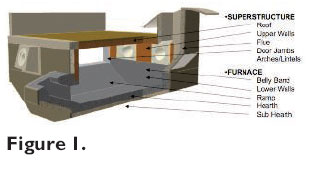
 Monolithics are used to line the metal and non-metal contact regions in typical melt-hold gas fired reverbatory furnaces. Each region is subdivided, as illustrated in Fig. 1, and each has a different set of operating conditions. Therefore, a variety of refractories are required for a complete furnace lining.
Operators are melting and holding a variety of fluxing materials, so the monolithics must cope with the specific chemistry present in the furnace. In addition, different operating practices (e.g., methods and frequency of cleaning) mean that diverse physical conditions can influence different parts of the furnace.
The diverse nature of the furnace environment means that aluminum producers need to maintain a complex and lengthy testing scheme for furnace linings. This is to subject potential materials to the full range of conditions that they are likely to experience in service. It is neither practical nor cost-effective to test materials for all types of conditions and so aluminum producers have developed a practical set of laboratory tests.
 The two main failure mechanisms that limit service life are chemical attack (corundum growth or corrosion from flux addition) and mechanical damage (ingot loading, cleaning practices or thermal shock). Producers have developed tests to simulate these as part of their approval programs.
We focused on the metal contact region, as this produces the most aggressive set of conditions and represents the most demanding part of the furnace in terms of lining performance. Corundum growth is the most significant threat in this area and therefore receives the most attention when designing and testing furnace- lining materials.
Corundum forms when liquid aluminum reacts with free silica in refractories. This transformation leads to a large expansion in volume, causing severe distortion and cracking of the lining:
[4Al (l) + 3SiOl2 (s) -> 2Al2O3 (s) + 3Si]
 The most prevalent laboratory test for corundum growth resistance is the aluminum ‘cup’ test. The test’s objective is to understand how different test conditions affect the behavior of the lining materials by evaluating how existing furnace lining materials behave when subjected to aluminum producers’ contact ‘cup’ test methods.
Testing, testing
The standard metal contact ‘cup’ tests of three aluminum producers are outlined here. These procedures are routinely used to assess the suitability of monolithic refractories for use in melt-hold furnace linings.
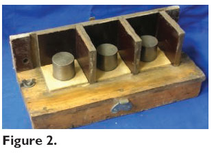
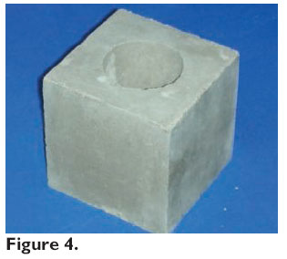
Method 1 — A series of 100-mm cubes are cast from compositions mixed at standard water addition (the mold is shown in Fig. 2; a cube is shown in Fig. 4.) Each cube has a 50-mm deep, slightly tapered hole (55 mm diam. at top, 53 mm at base.) Samples are set overnight, then demolded, cured, and dried at 230°F for 18 hours. Half the dried sample cups produced are then pre-fired to 2,192°F for 5 hours. Lids of the same material (25 mm thick) are made too, to minimize loss of volatiles.
Typically, 7075 alloy is used for testing, supplied as 52 mm bar and cut to 50 mm lengths. The cut alloy sample is inserted into the hole in the sample cup and the lid is placed on top, unsealed. Both as-dried and pre-fired samples are tested at the same time for comparison.
The assembled cups are heated in a kiln to 1,832°F at a rate of 302°F/hr and held at temperature for 100 hours. Natural cooling in the kiln follows. After cooling, the samples are sectioned vertically, dried, and visually assessed for the degree of metal penetration, corundum growth, or ease of removal of the aluminum and photographed.
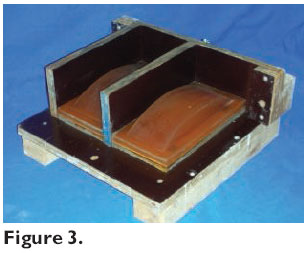
Method 2 — Following the supplier’s mixing recommendation, a standard brick size (23011476 mm) of the test material is cast into a mold that incorporates a curved face to form a cup shape with a maximum depth of 32 mm for holding the alloy (the mold is shown in Fig. 3.) After curing, the sample is fired according to the recommendation to 1,499°F with a 10-hour hold and cooled naturally in the kiln. Then, the curved cup section is roughened with a diamond saw to expose the refractory grain.
The cup sample is raised to 1,499°F in a furnace at a rate not exceeding 302°F/ hr. Meanwhile, 7075 alloy is melted in a silicon carbide crucible, heated to 1,499°F and sampled for analysis. Then. the molten alloy is ladled into the brick cavity at 1,499°F to about 3 mm below the top of the brick and held at temperature for 72 hours. The alloy is raked every half hour for the first three hours to remove the oxide film barrier at the metal/ refractory interface. After 72 hours the oxide formed on the top of the molten alloy is cleaned and a sample of alloy from the cup is taken for analysis.
Any remaining metal is poured off and the cup surface is cleaned with a Superwool blanket pad. The cup is air cooled and sectioned through the center (along the short axis) to assess degree of metal attack. The initial and final chemical analyses of the alloy are compared to determine pickup of silicon and iron.
Method 3 — Samples are prepared according to the supplier’s recommendations and cast into the same molds as used as Method 1. Following the same setting, curing, and drying process, half the dried sample cups are pre-fired to 1,472°F for five hours and half to 248°F.
Four test pieces are heated simultaneously in an electric furnace alongside a quantity of the test alloy in a crucible at 50°F/min to 1,472°F, ±41°F. 160 g of pure aluminum (>99.8%) is ladled into the sample hole and the cups are held at 1,472°F for 72 hours. The melt is stirred daily to break the oxide film formed, and afterwards is left to cool naturally in the furnace. It is cut diagonally and the cut face inspected for penetration and reaction with metal and photographed.
Assessing results
Three monolithic materials were tested using the three ‘cup’ test methods to assess how the different test conditions affect the outcome of the test results. None of the materials tested using Method 1 show any significant corundum growth, as would be expected since all three materials are routinely used in aluminum furnaces. One material, Material C, which was pre-fired to 2192°F, showed a thin layer of corundum formed at the interface with the metal and this suggests that corundum resistance begins to degrade as firing temperature increases. This behavior would have performance implications in service when furnaces are operated more aggressively.
Method 2’s results show no corundum growth on any sample at lower temperatures of 1,499°F, despite roughening of the contact surface to try to promote reaction. However, the alloy analysis reveals that silicon pick-up increases. ‘Cup’ test failures are normally accompanied by increased concentration of silicon and iron in the alloy after testing.
The trend for increasing silicon pickup matches the reduction in alumina/silica ratio in the material. As silica content rises, more Si is detected in the alloy.
As with Method 2, the results of Method 3 show no visible signs of corundum growth on any sample. The results indicate that testing at 1,832°F accelerates the corundum reaction and that prefiring the sample at higher temperatures can cause the non-wetting additive to react with other material constituents and to lose its effectiveness.
As all the materials studied are already in use in many furnaces, we would expect that all the materials tested would pass these cup tests and for most test conditions studied that has been observed. However, as the severity of the test conditions increases, more metal/refractory interaction has been observed.
This matches general operational observations where it has been noted that the refractory material starts to suffer from corundum growth in more aggressively run furnaces. According to these tests, metal contact performance appears to start deteriorating as temperature increases to 1,832°F.
In the past, such high test temperatures were considered unrealistic as holding temperatures tended to be well below this level. However, recently, as aluminum furnaces are pushed harder, chamber temperatures have risen and conditions have become more aggressive for the refractory lining. Therefore, test conditions that accelerate the reactions involved are now more valid.
In particular, corundum growth is often seen to start at hot spots in the furnace, where temperatures can be measured in excess of 1,832°F. This situation is exacerbated by exothermic reactions from salt and dross build-up on the lining. As industry needs have changed, so the furnace environment has changed and therefore the material test methods need to evolve to reflect this.
In light of modern aluminum test practices, testing temperatures of Methods 2 and 3 appear too low, as they do not accelerate corundum growth reactions adequately. Also, the high melt surface area in Method 2 promotes excessive dross formation and volatilization. Methods 1 and 3 use relatively small alloy samples, which also suffer from volatilization, but this can be controlled to improve test repeatability by covering the sample ‘cup’ with a refractory lid of test material.
‘Cup’ test results are further complicated when salts are introduced into the metal contact ‘cup’ tests. These studies have shown that resistance to corundum growth can alter considerably in the presence of salts and further investigation on this subject is being carried out.
Aluminum producers aim to increase productivity to remain competitive. This is normally achieved by using more powerful burners to melt the metal faster. However, this leads to increased metal losses as a result of surface oxidation and to larger heat gradients across the metal, leading to segregation of alloying elements and a reduction in metal quality.
These effects are countered by increased use of fluxes to suppress surface oxidization and increased stirring of the metal to achieve homogenization. Aluminum producers must ensure that their material assessment tests reflect the challenging conditions for the refractory lining, or the tests will produce unrealistic results and material selection may be compromised.
This investigation suggests that ‘cup’ tests using lower temperatures are not aggressive enough to assess lining materials in today’s furnace environment. Test methods must evolve in line with the furnace conditions they try to simulate.